The Race Begins!
Hare Part
Mold Design


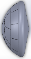
The hare mold was designed with a scale factor of 1.035 and is shown in the figures below. The part was designed with no draft as it is not necessary given the contours of the part. The parting line was placed at the largest outer diameter in the part. The parting surface was is on the outside of the part and it extends 0.2 inches from the part. The contours that make up the hare features are all located on the cavity. The locations of the mounting holes are based on the referenced mounting holes for the injection molding blocks that already machined. The sprue hole is placed above the part in the mold in both the cavity and core molds. The extrusion in the part, which is meant for the felt part of our design, is accounted for in the core mold, where extruded boss is placed.
Process Plans
Hare Part Core Mold
Step
|
Operation
|
Machine
|
Tool #
|
1
|
Rough Cut with 0.035” depth cuts
|
Lathe
|
1 (Face/Turn with Radius 0.0313”)
|
2
|
Finish Cut
|
Lathe
|
1
|
3
|
Groove Cut
|
Lathe
|
9 (Grooving Trepan with Radius 0.0385”)
|
4
|
Finish Cut
|
Lathe
|
7 (Turning Trepan with Radius 0.01”)
|
5
|
Finish Cut
|
Lathe
|
8 (Boring Trepan with Radius 0.01”)
|
6 (ejector pins)
|
Drill/Counterbore to 0.08” depth
|
MIll
|
9 (⅛” Ball Endmill)
|
7 (ejector pins)
|
Peck Drill to 1.1” depth
|
Mill
|
17 (Standard Drill - 0.12)
|
8 (ejector pins)
|
Reamed ejector pin holes
|
Drill Press
|
⅛” Reamer
|
9 (ejector pins)
|
Deburr
|
Hand Tool
|
Counterbore
|
10 (tail pocket)
|
2D Pocket to 0.100”
|
Mill
|
3 (⅛” Endmill)
|
Hare Part Cavity Mold
Step
|
Operation
|
Machine
|
Tool #
|
1
|
Rough Cut with 0.025” depths of cut
|
Lathe
|
11 (Large Bore radius 0.03125”)
|
2
|
Finish Cut
|
Lathe
|
11
|
3
|
3D Scallop
|
MIll
|
9 (⅛” Ball Endmill)
|
4
|
3D Scallop (eye of hare)
|
Mill
|
8 (1/16” Endmill)
|
5
|
3D Scallop (nose of hare)
|
Mill
|
8
|
6
|
Drill slot for runner
|
Mill
|
9 (⅛” Ball Endmill)
|
Photographs


Process Parameters
Ejector Pin Length
|
5.490
|
Shim Thickness
|
.074
|
Injection Speed
|
80 %
|
Injection Pressure
|
300 psi
|
Holding Time
|
6.0 sec
|
Holding Pressure
|
400 psi
|
Screw Drawback Speed
|
70.0 %
|
Shot Size
|
22.5 mm
|
Cooling Time
|
20 sec
|
Mold Open Position
|
120 mm
|
Clamping Pressure
|
123 kN
|
Injection molding parameter were at first kept at the default settings. The first thing we changed was the shot size. We first attempted a shot size of 20mm, but that didn’t completely fill the part (approximately ⅚ of the part filled) so we optimized it to 25 mm. At this shot size, the plastic was pushing out onto our felt tail. We were then given the suggestion to try without the felt and have the plastic completely fill the tail cavity. We optimized to 22.5mm and we found that the part looked adequate. The part was completely filled with few defects.
Summary of Learning Process
During the optimization process, the team learned how to optimize parameters for our yoyo to minimize defects and still achieve a snap fit between our parts. By decreasing the cooling time we were able to increase shrinkage which allowed for a better snap fit to our body part. We learned that if using insert molding, for a material such as felt, the compression of the material must be accounted for so that plastic does not fill the gap. To fix for this issue, the team decided to resurface the cavity mold so that the gap for the felt would be much shallower. This fixed the issue of the plastic getting into the gap that is meant for the felt piece.

Comments
Post a Comment